


updated 08-02-2014
from Tesla’s Flying Machine, page 1
Tesla’s Flying Machine
Page 2
“Tesla’s Flying Stove”
“Not the airplane, the flying machine,” responded Dr. Tesla.

A few weeks later, I traded these motors for 10,000 rpm 1/5hp motors.

Sept.12th, 1992
Second Tesla Space Drive Design
Since nothing is said about weight being an issue, my second
(all steel) frame was built to be rigid, not light-weight.

it was right after this that I figured out the speed
requirement and the variables that affect it
Third model, with 10,000 rpm ele. motors

The only expensive parts are the motors, (aluminum) pillow blocks, and mitre gears.
The pillow blocks, and mitre gears, combined, totalled $138.44. About a 2 foot square sheet of aluminum was less than $10. The shafts are also aluminum and cheap.
The shafts and pillow blocks are also, now, aluminum alloy. This model was fine but, the frame was just a little flimsy.

Note: I used the red/orange (Lovejoy) jaw couplings because they were a cheap easy way to attach weights on a shaft. I just replaced the set-screws with bolts. For a good close-up, click on the photo above (the 3 photos) to see an enlargement.
Experimenting out in the back yard, 1993

here I and a friend discovered the frame flexed a little

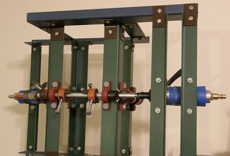
Final design: January 1994
using .090 inch aircraft aluminum ($9)
and 2 22,000rpm air motors ($50)

the frame is rigid and the motors are very light weight
I made the frame taller to accommodate longer arms and, slower speed requirements but, that was not necessary. However, there is an increased strength and reduced stress benefit to the double arms.
photographed on Fri., March 24th, 2006

Oct. 20th, 2007:
A few weeks ago +/- I tried it without any crossbars but, the weight and inertia were still too much for the motors. we got maybe 200 rpm but, we need maybe 600 to 800 rpm? I think the air pump where I am trying it, is not as strong as the one I used in Phoenix.
Nov. 2007:
I bought 2.5″ bolts and 1.5″ bolts so I have 2 more options. If the 2.5″ does not reduce the weight and inertia enough to enable the motors to get up some significant speed, I can try the 1.5″ bolts.
Cutting the length, and weight, in about half (from 4.75″ to 2.5″ bolts) reduces our net radius from about .1″ to about .025″ and our needed speed from about 600+ rpm to about 1200 rpm. Although it was an improvement, It just was not enough improvement and we switched to the 1.5 inchers. (see “December 2007” photo below) We started it up and the speed finally seemed significantly improved. A mechanic said it looked like it was going about 5 or 6,000 rpm. Great! Finally! Still, nothing more happened and we turned it off.
(we have no way of confirming how fast it was going – I think maybe only 1 or 2,000 rpm)
December 2007
Afterwards, I realized several potential problems. (1. The force may have been exerted downward instead of up (we need to try turning it upside down) and, (2. the 2 air hoses were adding weight to the system, holding it down. We need to prop the hoses up so that they do not add weight to the system.
Jan. 30th 2008:
We tried it again, right side up and upside down. We held up the 2 air hoses. But, no movement, no lift. It may be that we need 3-4000 rpm but are only getting 1 or 2000.
Testing at an auto body shop, Jan 30th 2008
 |
 |
June 30th 2008
If we got several thousand rpm, enough(?), then, it didn’t work. If not, then either a further reduction in the mass and inertia of the rotating weights and / or a change to stronger motors is needed.
Hopefully, we can get a sufficient speed increase by further reducing the weights & inertia. If not that, then by getting the weight of the motors off the frame by using couplers to extend the 2 shafts out beyond the frame.
March, 2009
I started getting calls from a TV production co. in Calif. wanting to put my flying machine on a Discovery Channel special.
I stopped at the auto shop, told them about it. They told me that they have gotten a new, stronger, compressor. Now is the time to try again!
Saturday, March 21st, 2009
Saturday was a disappointment. The new compressor provided significantly more power than the old one. The speed was much improved, very impressive, “more than enough”. This time I do think it was up to 3 or 4000 rpm, if not more. However, the weather was bad, raining, and I only did half the test. Still, it did not move. There was plenty of speed in the rotating masses. So, either I had it upside down, 50-50 chance of that being true, since it is totally symmetrical, or there is some stumbling block, some criteria I have not thought of.
Wednesday, July 22nd, 2009, 9am
Tried it again. The speed, again, seemed enough. But, again, I can’t be sure, and it did not go up.

2011, Footnote:
A frame is cheap, a person can design and build one around motors they come up with, the smaller the better, perhaps. Smaller motors can generally run at higher speeds. Extension rods, longer rods, can be used to get the motors off the system, and that will reduce the total weight greatly.
Here is one Marcelo B. built. Glad to hear from him.
back to Tesla’s Flying Machine, page 1
Hi I hope you are still working on it … here is a tip if you think it doesn’t move: try getting some high precise digital scales and put your machine on them you will see the difference in weight if it moves at all if the weight is still the same on 5k rpm then there is some bigger issue to it. It may sound stupid but it aint ;)
It is a thoughtful idea. I think someone else mentioned it in a comment earlier also.
Until a year ago, it vibrated, too much to get that kind of reading, but now (last year) that I have shortened the bolts “eccentrics” even more, it has picked up significantly more speed and seems to have stabilized a lot. That is a good sign.
Tesla uses two motor to avoid countertorque, that’s because the frame has free movement either to rotate or oscillate, I think it wobbles, and the absence of mechanical elements this wobble is natural because of the rotating weights.
Marcelo Bertaina (xxxxxxxxx@gmail.com) for your protection
The weights generated centripetal acceleration, while the frame is tilted with each upward and downward movement of the weights, if allowed to frame wobbling at 360 degrees (like a coin that falls to the ground) will appear a vertical lift force (f sin a) is a centripetal force component. Another force component of the centripetal horizantal (f cos a) is holding the total weight of the machine.
Now the critical point is that the frame should wobble to the same frequency with spinning the weights, theoretically possible, physically difficult. So I suggest you try hanging the frame of a dynamometer and not on a rigid surface please.
Thank Mr Greg Smith .
Marcelo Bertaina , Río Cuarto ,Cordoba, Argentina.
Tesla’s Flying Machine
Turning it on its side wouldn’t change anything all of the 4 weights would remain the same, there all pulling and pushing at the same rate, be it on its side or upside down.
Rotating it on its C/L wouldn’t change it either, the same forces would be at work just in a different aria. Unless the gyro affect changes all the propertys, I dont know. Whats flawed here is everything is stable, all the forces are reacting agents one another.
You may need to change the weights during motion and I would think that the an equalization of spinning weights and the whole mass would need to be close to equal keeping the speed down for the machines movement with increased speed.
I wonder if the 2 motors we not connected but worked 2 weights on there own, basic everything else the same, slowing one motor or speeding it up may give it a diagonal push.
I will say one thing its an interesting concept and if Tesle thought it would work it I’m sure it will but not in this present form. Just my opinion.
Charles
If all forces were stable, there would be no “machine” or motor. There is an induced centrifugal force which has no counter-balancing centripetal force. The device, its center of mass, is spinning like a top. It is just sitting there, but its center of mass is not.
an update? i’d love to see your machine work. i really really really really really want to see it work lol. good luck with it mate. Its about time technology advanced some more
William Smith is correct. The entire system must rotate about the x axis. It can be done through gearing .
I believe a great deal of effort has gone into trying to understand a very a simple design.
There is no magic. This is a simple impulse drive. The force is generated by the rotating masses (eccentric masses) about each shaft. When the rotating masses line up, the force vectors are added. When you rotate the massed about the x axis, they line up every 90 degrees of rotation. Thus, you can cause the forces to line up in any direction in the 360 degrees of rotation. The only discrepancy I have found in the instructions is that the force vector is not out of the page but parallel to the page. Also there is a great deal of wobble. You must enhance the design to cancel out the wobble forces.
I would not suggest trying to fly this contraption until you completely test the impulse drive on the ground. Use it to push or pull your car around and find out how long the gears will last or where lubrication is necessary and how to change directions.
Also, Tesla never patented his flying stove. So the patent has been falsified. Compare Tesla patents and signatures and you will see.
Good luck and be safe.
Also, have fun.
Bill Santangelo
I was looking at your website about Tesla’s Flying Machine.
I think there was one aspect of the invention that you overlooked, which is why your prototype didn’t work. In the patent it showed an arrow indicating that the whole apparatus rotates around the center of mass. I don’t think you were rotating the whole apparatus. It wouldn’t be possible with compressor hoses, anyway.
If you rotated it in sync with the weights spinning, you will have more centrifugal force on one edge than you will on the the opposite one. One weight will be hanging outward toward the pull of the centrifugal force while the other will be pulled inward. The weight that is hanging outward will have much more pull on it than the one that is pulled in.
Alternatively, instead of motors, the spinning mechanisms could be coupled to the central shaft and spun off of that. When you spin the whole apparatus, it would cause the weights in the middle to start spinning in sync with the apparatus’ spin.
Do you understand what I am saying? I can try to draw you a picture if you like. I believe if you get the whole apparatus spinning in sync with the weights (weights spin 1 rpm per 1 rpm of the whole apparatus spinning), then this will work. Don’t give up.
Sincerely,
William Smith
My thought was that if you were able to place the machine on top of 4 load cells (1 at each corner is probably easiest), you could monitor the weight and the forces created for a length of time while increasing the speed. You should be able to average everything out. A fourier transform would be able to remove the harmonic motion in the data, but is unnecessary. Averaging would work.
After perusing your site, I wanted to ask if you might put a scale or some scales under your machine to see if its weight decreased or increased noticeably while it’s running. You’ve put so much work into it, that I would think that a mechanical engineer prof at a nearby university would likely have some load cells and a data acquisition system where you could weigh the system while it’s running, and see if the average weight dropped. If you mentioned Tesla, the blue prints, and approached it right, I believe someone would be glad to try it out. They’ve got grad students to throw at these things.
G’day,
I was just reading about someone trying to construct a Tesla flying machine on http://www.tesla-flying-machine.com.
I am no expert in physics but I would be very curious to see that if the whole device was to spin on a vertical shaft while the eccentrics were in motion, would opposing forces be created resulting in lift? Kind of like having two of the same poles on separate magnets repelling each other.
I’ve noticed in the photos that the machine has only been powered up when sitting stationary.
It would be interesting to see if the arrow in Tesla’s drawing next to the centre of mass is actually a rotational direction of the entire device, a possibility worth exploring/eliminating?
Food for thought
Take care
Howard.
I am currently a college student and taking a business course on entreprenuership and innovation (completely irrelevant to Tesla’s work). In my spare time I stumbled across your website on the flying machine and was very intrigued.
In my coursework we focus on cognition, cognitive fitness, and innovative ways to look at business problems. It bother’s me that a lot of these business minded persons’ rip off the scientific method and call it a new unique process. Anyways, all that is besides the point.
I tried to apply some of the principles of my course when looking at your experiments. It occurred to me that your experiments used motors that were plugged in. But, would Tesla maybe have planned on powering his machine wirelessly through the use of a large coil like the ones at Wardenclyfe or Colorado Springs? [*1] Could he have intended to power it wirelessly not using a coil but just tapping the natural electricity of the earth? [*2] Could the corded motors have affected your ratio’s and the gravitational effects of the experiment? [*3] I don’t know if you’ll get this e-mail or if you’re even still interested in the flying machine. But, if you are and think this could amount to anything please contact me back. Thank you and happy holidays.
Sincerely,
Charlie Drury
It occurred to me on reading of your project and reviewing Tesla’s drawing and description that there may have been room for misinterpretation (or perhaps intentional misdirection 8~). The phasing of the rotating weights might have been intended to be in phase rotationally; that is, they should all be facing either down, or inward, or up, or outward together.
I thought of the skater spinning with arms extended who draws her arms inward and is accelerated in rotation. Imagine four such skaters bound to the center of mass X viewed from the side(s). If the weights move downwards on the outward swing, and upwards on the inward swing; that should create a force upwards on each “skater” (the C of M called X). The vibration at low speed would only be up and down since the center of mass does not then change in the horizontal plane. Hope this helps you.
Longer side shafts and smaller weights more in proportion to Tesla’s drawing would likely work best. For power, perhaps two of the powerful and small R/C brushless motors (cheap on Ebay) and controller(s) might be adequate when powered by lithiums …… and an R/C radio if it all works!
WB from Canada
PS: On second thought, the rotation should likely be reversed; that is, downwards on the inside swing. -WB
I swear I watched that movie but heck if I recognize the lengths on those arms already exceeded the center of the internal area. I realized it was a non-issue a bit after I wrote the first time, so I’m just catching up.
One other thought, that you mentioned, was adapting the weights to lessen drag. That could help increase RPM but then I had one other, silly thought when considering the reshaping of the weights. What if the design was to attempt to add a lift component through the shape of the weight? Make the weight have the cross section of a typical wing and only allow the lift component to occur when the weight/wing passes over the force vector that would add to the lift. Again, something I can play with in my free-time, which appears to be non-existent.
I like your Tesla flying device replication. I’m interested in his technology and would like to build that “flying stove” too. I was wondering if you have any instructions, drawings or parts lists for building it. That would help a lot.
I read with interest your article in the current issue of Extraordinary Technology about your attempts to build the Tesla “Flying Stove” propulsion system. The one comment I have is that, in the picture of your final design, it appears that the arms (eccentrics) are long enough that they would extend well beyond the center of the frame (point X of the figure from Page 31 of /Tesla, Man of Mystery/). Wouldn’t that greatly decrease the component of the axis of orbit of the center of mass parallel to the plates and thereby cause less of the force generated perpendicular to the orbit to be in the desired direction? In other words, wouldn’t that cause more of the force to be directed sideways rather than up or down? I’d think that the longer the arms are with respect to the dimensions of the frame, the less efficient the device will be at directing force in the desired direction (that the efficiency would be inversely proportional to that ratio, up to a point). In Tesla’s diagram, the eccentrics are only about 1/4 as long as the length of the sides of the frame. I think you may have gone astray when you deviated from that ratio.
Sincerely,
Leland Hosford.
P.S. Your deviation from that ratio is probably also the reason why your device “started shaking more, not less” as you reduced the weights and got it spinning faster. It is because the vector of force perpendicular to the orbiting center of mass would have been alternating greatly between different sideways pointing directions as the device spun up. You need to do your best to minimize the sideways components of that force vector, not increase them.
P.P.S. I realized that in my original comment, I really meant “the component of the plane of the orbit of the center of mass parallel to the plates” (“plane” rather than “axis”, which would be perpendicular to the plane). -Leland Hosford.
I have Autocad LT 2007 and was going to draft up something for your consideration. Before doing so I wanted to see if there were physical limitations. If your file can be converted or just sent in Autocad format, I can work with your drawing first.
I’m a semi-retired civil engineer ( bio at http://www.rw2LLC.com ) and my background in dynamics is more than rusty, but I believe we can significantly increase the radius of IL CoM, and reap whatever benefits we can from that. I also would suggest setting the unit on it’s side, on a wheeled device to see if we can get lateral movement.
Consider on your diagram, looking at the device in plan view as it’s drawn, north being at the top where the weight is extended away from the center of the device. Now consider the arm for that weight being long enough to extend the weight to rotate almost to the cross bar at the south end. The south end bar has TWO weights, each approx half the weight of the north weight. These are situated equi-distance from the north/south centerline. The arms for the south would be (volumetrically) about half of the north. Basically just to make the two weights (and the forces due to wind resistance) maintain the same center of gravity (terminology?) as the single north arm, but of course in opposition. Likewise one east/west arm is long, and the opposite side has two “half” weights, thereby allowing the weights to occupy nearly the entire inside space.
Just drawing this and confirming the track of IL CoM and the possibility that this physically can operate would be enough for me at this moment, but, I pose a couple other possible ideas.
1. Having this attached on it’s side, to a “sled” of sorts, we are attempting to generate the linear motion along the horizontal path. Would multiple units, each generating the same linear force, operate in an additive fashion? Say 4 units all set to develop a linear force along the same horizontal direction?
2. By using fewer motors, running say 4 units from 2 or 4 motors, weight may be reduced, but here is the other thought. Although all units are rotating the weights in the same way and same speed, “tune” or “set” the weights to work against each other. Setting 2 units by 2 units, “mirror” the horizontal weights so they are opposite each other. Likewise for the weight spinning vertically. The vibration horizontally would cancel as well as the vertical. Obviously I am not suggesting building 4 units now, although I am curious about your thoughts on my ideas.
I am impressed with your physical work on the device though, and hope perhaps I can help with some other ideas.
Rick Warden
PS I got to thinking about the configuration and wonder, if 4 LONG arms would even collide? Perhaps I’m missing something without drawing it. If that could be a possible configuration, would the centers of gravity and the resulting motion make a better device?
I was thinking how nice it would be if we knew how Tesla transmitted his energy to his “receiver” as in Wardenclyffe (sp?). No cord necessary!
I believe I used turbocad back in the early 90’s but have long since lost the original file(s) and only have scanned printouts now.
Watch the movement on motor in motion and see that they never cross paths. Alternating 1 & 2 weights is not necessary.
I did try setting it horizontal, long ago but, realized it is like magnets approaching each other. Only the distance matters, not the direction, up down or sideways. The forces here are much greater than gravity, even greater than magnetism.
There are “economies of scale” and cost: Build the smallest possible with motors that are just barely “up to the task”? – the smallest lightest-weight possible motors that can still do the job for only the shortest amount of time? Your 2 or 4 units ideas are valid but introduce more complex issues that may be counter-productive. Someone could try it.
I am hoping that by cutting the weight of the masses in half, I will more than quadruple the speed the motors can generate. I have already gone from 0 to at least a thousand rpm, maybe more. Reducing the weight by half only increases the required speed by about 1.3 “economy of scale”
I really enjoyed reading through your web site. Just thought I’d drop a note on how I see this working…
I think the machine you’ve build should be turned on edge. The eccentrics all should turn inwards toward the center of mass. I think
the Tesla drawing is very incomplete for many reasons, partly because he didn’t want to give away to much. It may be that he intended two of
those working together in gyroscopic form. I’m still unsure of the lift part and control of such w/o there being much more to the generation of fields. I also would imagine he intended to draw power from a Tesla coil, like wardencliffe. Also did he intend to use electricity and magnetic elements? Or was this purely mechanical and driven in direction by the speed of the eccentrics moving. I would see the eccentrics pulling the center in whatever direction the whole device was angled.
When looking at it in purely mechanical form, weight would be significant. When looking at it from a magnetic perspective, weight still plays an issue, but would be relative to the fields being produced and the earth’s gravitational effect on it. Still a weight issue.
When I read the description, I see the whole frame you built rotating around the center of mass based upon Tesla’s description.
Regards,
Jeff
The machine itself is mechanical but, he may have intended to power it from wardencliffe.
I have ordered the material to make this contraption. If what I am thinking is right you need the electric motors to start it then it will take over. Then the problem is to stop it. Using the electric motors as electric generators and using resistive loads on the output will act like a brake.
gravity will pull it back down, or, in space, where there is little gravity to pull or stop it, running it in reverse will act as a break.
I will mention about your flying machine in a conference to be held in Belgrade in the month of october.How much amount it will take to conduct further research in this field.I want ppeople should get benefit of flying machine of tesla as soon as possible.
In the name of Allah the most gracious and ever merciful.
I am an Indian. I am interested to mention flying machine of Tesla in a conference in Belgrade in October. I want mankind should get benefit from your technology. please help me.