


updated 08-02-2014
from Tesla’s Flying Machine, page 1
Tesla’s Flying Machine
Page 2
“Tesla’s Flying Stove”
“Not the airplane, the flying machine,” responded Dr. Tesla.

A few weeks later, I traded these motors for 10,000 rpm 1/5hp motors.

Sept.12th, 1992
Second Tesla Space Drive Design
Since nothing is said about weight being an issue, my second
(all steel) frame was built to be rigid, not light-weight.

it was right after this that I figured out the speed
requirement and the variables that affect it
Third model, with 10,000 rpm ele. motors

The only expensive parts are the motors, (aluminum) pillow blocks, and mitre gears.
The pillow blocks, and mitre gears, combined, totalled $138.44. About a 2 foot square sheet of aluminum was less than $10. The shafts are also aluminum and cheap.
The shafts and pillow blocks are also, now, aluminum alloy. This model was fine but, the frame was just a little flimsy.

Note: I used the red/orange (Lovejoy) jaw couplings because they were a cheap easy way to attach weights on a shaft. I just replaced the set-screws with bolts. For a good close-up, click on the photo above (the 3 photos) to see an enlargement.
Experimenting out in the back yard, 1993

here I and a friend discovered the frame flexed a little

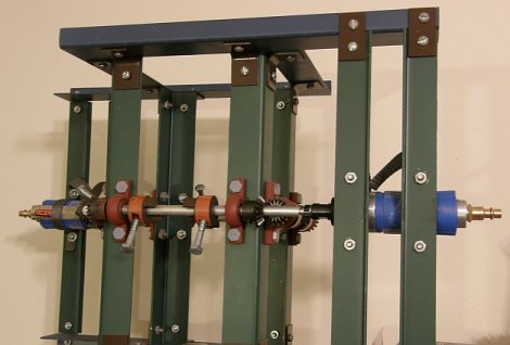
Final design: January 1994
using .090 inch aircraft aluminum ($9)
and 2 22,000rpm air motors ($50)

the frame is rigid and the motors are very light weight
I made the frame taller to accommodate longer arms and, slower speed requirements but, that was not necessary. However, there is an increased strength and reduced stress benefit to the double arms.
photographed on Fri., March 24th, 2006

Oct. 20th, 2007:
A few weeks ago +/- I tried it without any crossbars but, the weight and inertia were still too much for the motors. we got maybe 200 rpm but, we need maybe 600 to 800 rpm? I think the air pump where I am trying it, is not as strong as the one I used in Phoenix.
Nov. 2007:
I bought 2.5″ bolts and 1.5″ bolts so I have 2 more options. If the 2.5″ does not reduce the weight and inertia enough to enable the motors to get up some significant speed, I can try the 1.5″ bolts.
Cutting the length, and weight, in about half (from 4.75″ to 2.5″ bolts) reduces our net radius from about .1″ to about .025″ and our needed speed from about 600+ rpm to about 1200 rpm. Although it was an improvement, It just was not enough improvement and we switched to the 1.5 inchers. (see “December 2007” photo below) We started it up and the speed finally seemed significantly improved. A mechanic said it looked like it was going about 5 or 6,000 rpm. Great! Finally! Still, nothing more happened and we turned it off.
(we have no way of confirming how fast it was going – I think maybe only 1 or 2,000 rpm)
December 2007
Afterwards, I realized several potential problems. (1. The force may have been exerted downward instead of up (we need to try turning it upside down) and, (2. the 2 air hoses were adding weight to the system, holding it down. We need to prop the hoses up so that they do not add weight to the system.
Jan. 30th 2008:
We tried it again, right side up and upside down. We held up the 2 air hoses. But, no movement, no lift. It may be that we need 3-4000 rpm but are only getting 1 or 2000.
Testing at an auto body shop, Jan 30th 2008
 |
 |
June 30th 2008
If we got several thousand rpm, enough(?), then, it didn’t work. If not, then either a further reduction in the mass and inertia of the rotating weights and / or a change to stronger motors is needed.
Hopefully, we can get a sufficient speed increase by further reducing the weights & inertia. If not that, then by getting the weight of the motors off the frame by using couplers to extend the 2 shafts out beyond the frame.
March, 2009
I started getting calls from a TV production co. in Calif. wanting to put my flying machine on a Discovery Channel special.
I stopped at the auto shop, told them about it. They told me that they have gotten a new, stronger, compressor. Now is the time to try again!
Saturday, March 21st, 2009
Saturday was a disappointment. The new compressor provided significantly more power than the old one. The speed was much improved, very impressive, “more than enough”. This time I do think it was up to 3 or 4000 rpm, if not more. However, the weather was bad, raining, and I only did half the test. Still, it did not move. There was plenty of speed in the rotating masses. So, either I had it upside down, 50-50 chance of that being true, since it is totally symmetrical, or there is some stumbling block, some criteria I have not thought of.
Wednesday, July 22nd, 2009, 9am
Tried it again. The speed, again, seemed enough. But, again, I can’t be sure, and it did not go up.

2011, Footnote:
A frame is cheap, a person can design and build one around motors they come up with, the smaller the better, perhaps. Smaller motors can generally run at higher speeds. Extension rods, longer rods, can be used to get the motors off the system, and that will reduce the total weight greatly.
Here is one Marcelo B. built. Glad to hear from him.
back to Tesla’s Flying Machine, page 1
Tesla had planned on powering his devices wirelessly. Is it possible that the rotating weights used were magnets set to repel, given extra power using a coil? His motors would’ve also been powered wirelessly. Just a thought.
As in the reply above, he very well could have intended to power this wirelessly … at least until Morgan cut off his funding and had Tesla’s Wardenclyffe tower destroyed!
The weights in the device itself do not approach and recede, but stay relatively distant from each other … so probably not.
-ed
Tesla’s design is as simple as building lego blocks.
I have made my own design using the same priciple but using a simpler method and a different aproach.. This guy is genious.. Has anyone built the system as above and had it rotating around the center of gravity as Tesla intended?
Note that… Oh snap.. whait.. You guy’s havent.. that’s why I havent seen a working model.. and it’s not on the news everywere.. There is no such thing as time travel time is a man made idea of development. you can not rewind a process.. But this “motor” wil make space travel a breez. Imagine replacing fuelcells on a ship with oxygen and using only solar pannels for motion (electric).. You could visit Mars as a test run …
If you use this motor for propultion. Your tracktor will never get stuck in the mud again..
This may seem somewhat naive, but have you considered that Tesla might have designed this machine to run on his electromagnetic motor? It would be an undertaking in itself, but if you could build one, perhaps it would give you that last little something that isn’t there.
Not naive at all, very possible. see all our pages on Tesla.
– ed.
Tesla would use its turbines of 35,000 rpm, then I think the 4 axes should be smooth, without protruding inertial masses, the masses would be an imbalance of axes (bottom hole in the middle of the shaft). The configuration would be different from the scheme, imagine…
My machine is a crude model of how it should work, we are still far.
To visualize the inertials mass are N,S,E,W, the gc is orbiting and has horizontal tangential speed , i.e. when gc is near side S, the E and W mass ( up and down) should tilt the discal plane of turn ( not neccesary the frame). Now the tangential speed is not more horizontal, have a angle, this change of speed is vertical acceleration and so for each point of path of gc. If this happens then the device work, but if tangential speed always is horizontal then no work.
I have always been a fan of tesla and have also always been fascinated by the affects of centrifugal force. this article really sparked my imagination and i had an idea that i think you should try. the whole system works on the idea of a set of masses rotating at different stages to cause a form of “spinning to affect”, i dont think this machine was designed for lift as much as holding an object against the pull of gravity. at the moment your device has its energy being put into stopping the device from moving on its horizontal plane, i wonder what would happen if the entire assembly was spun from its centre and instead of electric motors at the corners of the frame you just simply “gear” it to the central drive shaft. doing this would allow you to spin on another axis and you could in theory achieve a greater rpm.
Please hang it on a scale and measure its weight while running. The produced acceleration may not be enough to lift it, but it may be enough to be measured by a simple hanging scale.
Thought of it. The vibration renders the scale/balance inoperable.
-ed.
The tilt of frame is seen like vibration and the inertial mass not is unbalance. I dont know like send picture and video, but appear in image google ( tesla flying stove)and you tube.
I build a device too. no effect was observed. the center of gravity girate in circle is true but remain in horizontal plane while the innertial mass tilted the frame.
Send us a picture of it (a close-up) so we can see it … even a photo of you running it!
If the weights (bolts?) are the same, and mounted as shown, then for each one spinning in one direction, there is another spinning in the opposite direction. Either something is out of balance, or you got a reaction of some other kind. (!)
– ed
I think I may have found the missing components needed for this machine to be effective…consulting with some engineers tonight to get some inputs. Will get back to you. This was an awesome article(s). I have read it several times. Thank you.
Tesla that sly fox has fooled you all !! Tesla gave Otis Carr all the info on his flying machine he and Ralph Ring and others built many small machines that flew. when they built a forty footer it turned out to be a time machine that was flown all over California. taken buy the powers that be it is now in area 51. check out Ralph Rings web site you will be amazed
Have seen it and been disappointed. It is too complicated, and expensive. No one has done anything with it since. Praise Tesla for passing on the knowledge for it, but what Tesla offers here, in his “flying stove” is simpler, cheaper, and has a better chance of being accomplished.
Is there a video of any of your experiments on YouTube? I’d love to see one but could not find any. If there are none, will you post any in the future?
It spins so fast, you cannot see anything, as you can imagine, however, I do have a large, slow motion, display of it, where you can see the arms spinning very slowly and see the offsets between the weights on the opposite sides and how they are synchronized, etc..
See page 3
Adding the top plate makes the center of gravity spin around in the center between the four axis.
Now, if you take Tesla’s original design, the center of gravity will spin around BELOW the axis, which should create a greater wobbling until the whole thing stabilizes itself – this could make a lot of difference, and if I were you I’d try with the larger weights and only a base plate.
The device will still be unbalanced considering the placement of the motors, but that may be an inherent design – it could be worth trying with weights matching the weight of the motors at the ’empty’ corners, as well.
Good luck in either case!
Thanks. Using only a base plate was how I got started. From the very first photo at the top, it can be seen that a top plate was not added until later. Also, the weights were much larger and heavier in all earlier experiments. The 2 motors are placed so that it is totally balanced and symmetrical.
if you look closly at the original page containing the insttustions there seems to be writing on it even when you print it. error? or somthing tesla coded? check it out
Suggestion: Instead of putting your flying stove on the ground, set it on a bathroom scale to measure any increase or decrease in the weight of the machine at various rpm and eccentrics.
Or you can make a simple balance using a long plank resting on a center pipe with your machine on one end of the plank and a counterbalance weight on the other end. Any change in the weight of your machine will be easily seen.
This would also nullify concerns as to the total weight of your machine in these early stages of design and experimentation.
thought of it. The vibration renders the scale/balance inoperable
-ed.
great job, keep going.
Hi guys, you did a real good job gathering together on this subject, (sorry for my spelling in english). I just want to tell you that this machine really torment me from few years (when i first time hear about it) and i almost twist my brains out in the strugle to find out how it works … and here i’m in this lucky night ..finding your site and having some revelations.
Ok, coming back to the subject, if i understood well there are some important things to be pointed out:
1) the whole table with everythings on it should gyrate(otherwise no “effect” occur)
2) this “compartementalising” of the design in 4 parts it seems pretty peculiar for me because after reading the comments that visitors have made it (especialy a particular one) i had a revelation-the comment was about introducing magnets instead of just mecanical eccentric masses-because i read in the last years internet literature about montauk and stuff but this design remembers me of well known “delta T antenna” which was a pretty similar device, but instead mechanical drive forces the last one have been powered purely electricaly.
3) other resemblance that stroke me was that it could be compared with a “tetra polar magnet” by it’s way of functioning. (this term is extracted from occult /alchemy terminology…see Franz Bardon)
4) it remembers me some explanations about philadelphia experiment wich involve Einstein in that experiment triyng to solve his U.F.T. (unified field theory).the theory of the theory stipulates that electromagnetic field was “geometrized”, which exactly means planes separation of forces x,y,z, (via 3 coils-shaped as an octahedron each plane from x,y,z, has a driving force).
Actually in the “Montauk” literature this device has other purpose than fliyng, was a kind of time witness, for the entire philadelphia exp. time witness meaning a perfect time 0 generator,wich brings back the whole ship in the time that it belonged (1943) not elswhere or in random time spaces dimensions.
Maybe you will tell me that i`m dreaming, while you (guys) are concerned with precise /matemathical/mechanical , calculations about this machine…but don`t forget, the Tesla himself was a dreamer also (read biography), and a weird person too.
hope you find interesting my “associations”, bye.
Adrian
by the way, Tesla was involved in the Philadelphia experiment till he realized it was dangerous, people would get hurt, and dropped out.
I suggest an axis on two bearings through the center of the box… like a gyroscope. Then turn you motors on and behold my friend. Tesla was a great man; he used several input sources for many of his devices. Some he never included in his patents at his lawyer’s advice.
I can see that leaves fixed the center of gravity, then (the frame) has a translational motion and the weights describe an elliptical trajectory with a elliptical plane tilted and horizontal axis, so the angular velocity of weight is not constant then the angular acceleration is different zero, there are forces but I can not determine the direction or if they are in balance.
The center of gravity is “orbiting” in a horizontal circle. read again and see page 3: “Flying Machine pg.3”
I apologize, I didn’t read all the comments just yet (I’m still reading). However When I first looked at Tesla’s original drawing you had I didn’t see weights, but instead I saw magnets, with the shaded side being the common polarity. Have you tried it with magnets instead? I hope this helps, and keep up the work. I wish I had the initiative you had. Good luck!
Interesting. No, had not thought of that. (Hummm???). . . Thinking more about it, think what would an orbiting magnetic field create? I have no idea, but the thought is interesting PS it will probably also include changing the orientation of the ‘eccentrics-now-magnets’ so that it does not generate a circular orbit. … up and down? … an oscillating field?
2010-10-29: note: an electro-magnetic coil gets its power from electrons in orbit. Here it is the entire atom-molecule in orbit. So, I think it is counter-productive – in this application, but change it to oscillating or … who knows?!
Hi
Your experiments are fascinating. There is something I read which it said the same opposite must be created.
Does this mean that you build 8 not four weights spinning as in the design. In other words place them back to back on there bases. Each nullifying the other creating a more powerful force. I may have this vision wrong. Also Tesla implied he would use his turbines to power the drives. Perhaps two or four model Tesla turbines would give you the power you need. My regards
What you describe, will cancel the forces. (?)