


updated 08-02-2014
from Tesla’s Flying Machine, page 1
Tesla’s Flying Machine
Page 2
“Tesla’s Flying Stove”
“Not the airplane, the flying machine,” responded Dr. Tesla.

A few weeks later, I traded these motors for 10,000 rpm 1/5hp motors.

Sept.12th, 1992
Second Tesla Space Drive Design
Since nothing is said about weight being an issue, my second
(all steel) frame was built to be rigid, not light-weight.

it was right after this that I figured out the speed
requirement and the variables that affect it
Third model, with 10,000 rpm ele. motors

The only expensive parts are the motors, (aluminum) pillow blocks, and mitre gears.
The pillow blocks, and mitre gears, combined, totalled $138.44. About a 2 foot square sheet of aluminum was less than $10. The shafts are also aluminum and cheap.
The shafts and pillow blocks are also, now, aluminum alloy. This model was fine but, the frame was just a little flimsy.

Note: I used the red/orange (Lovejoy) jaw couplings because they were a cheap easy way to attach weights on a shaft. I just replaced the set-screws with bolts. For a good close-up, click on the photo above (the 3 photos) to see an enlargement.
Experimenting out in the back yard, 1993

here I and a friend discovered the frame flexed a little

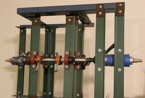
Final design: January 1994
using .090 inch aircraft aluminum ($9)
and 2 22,000rpm air motors ($50)

the frame is rigid and the motors are very light weight
I made the frame taller to accommodate longer arms and, slower speed requirements but, that was not necessary. However, there is an increased strength and reduced stress benefit to the double arms.
photographed on Fri., March 24th, 2006

Oct. 20th, 2007:
A few weeks ago +/- I tried it without any crossbars but, the weight and inertia were still too much for the motors. we got maybe 200 rpm but, we need maybe 600 to 800 rpm? I think the air pump where I am trying it, is not as strong as the one I used in Phoenix.
Nov. 2007:
I bought 2.5″ bolts and 1.5″ bolts so I have 2 more options. If the 2.5″ does not reduce the weight and inertia enough to enable the motors to get up some significant speed, I can try the 1.5″ bolts.
Cutting the length, and weight, in about half (from 4.75″ to 2.5″ bolts) reduces our net radius from about .1″ to about .025″ and our needed speed from about 600+ rpm to about 1200 rpm. Although it was an improvement, It just was not enough improvement and we switched to the 1.5 inchers. (see “December 2007” photo below) We started it up and the speed finally seemed significantly improved. A mechanic said it looked like it was going about 5 or 6,000 rpm. Great! Finally! Still, nothing more happened and we turned it off.
(we have no way of confirming how fast it was going – I think maybe only 1 or 2,000 rpm)
December 2007
Afterwards, I realized several potential problems. (1. The force may have been exerted downward instead of up (we need to try turning it upside down) and, (2. the 2 air hoses were adding weight to the system, holding it down. We need to prop the hoses up so that they do not add weight to the system.
Jan. 30th 2008:
We tried it again, right side up and upside down. We held up the 2 air hoses. But, no movement, no lift. It may be that we need 3-4000 rpm but are only getting 1 or 2000.
Testing at an auto body shop, Jan 30th 2008
 |
 |
June 30th 2008
If we got several thousand rpm, enough(?), then, it didn’t work. If not, then either a further reduction in the mass and inertia of the rotating weights and / or a change to stronger motors is needed.
Hopefully, we can get a sufficient speed increase by further reducing the weights & inertia. If not that, then by getting the weight of the motors off the frame by using couplers to extend the 2 shafts out beyond the frame.
March, 2009
I started getting calls from a TV production co. in Calif. wanting to put my flying machine on a Discovery Channel special.
I stopped at the auto shop, told them about it. They told me that they have gotten a new, stronger, compressor. Now is the time to try again!
Saturday, March 21st, 2009
Saturday was a disappointment. The new compressor provided significantly more power than the old one. The speed was much improved, very impressive, “more than enough”. This time I do think it was up to 3 or 4000 rpm, if not more. However, the weather was bad, raining, and I only did half the test. Still, it did not move. There was plenty of speed in the rotating masses. So, either I had it upside down, 50-50 chance of that being true, since it is totally symmetrical, or there is some stumbling block, some criteria I have not thought of.
Wednesday, July 22nd, 2009, 9am
Tried it again. The speed, again, seemed enough. But, again, I can’t be sure, and it did not go up.

2011, Footnote:
A frame is cheap, a person can design and build one around motors they come up with, the smaller the better, perhaps. Smaller motors can generally run at higher speeds. Extension rods, longer rods, can be used to get the motors off the system, and that will reduce the total weight greatly.
Here is one Marcelo B. built. Glad to hear from him.
back to Tesla’s Flying Machine, page 1
His idea works I have picture of it flying. Shape is not part of equation any shape any weight it will pick it self up.
I think I see the problem with your design the one work had the weights at different angles than yours from your pics it looks like they might not do much more than spin around. I will try to put diagram of the one I seen in here along with how it was explained to me .
Fc= m.r.(ω^2) centrifugal force
Vt= ω .r tangential speed.
If increase the mass (m) of pendulums, increase centrifugal force and is bad to frame resistant. If increase the rpm ( ω angular speed) increase Fc in quadratic magnitud and tangential speed rice linear. If increase the radius, Fc not increase, but Vt increase and this parameter is the important. It is possible build the axes in shape of >> two “vees”, don’t straight, the left pendulum overpass spin line of pendulum right.
I believe to make this machine work the eccentrics need to be sliding weights, so that at the top of their strokes they are further away from their rotating axis than at the bottom of their strokes. One way to achieve this would be for the sliding eccentric weights to be permanent magnets ( say N outside and S inside ). At the centre of it’s axis would be another permanent magnet fixed vertically with S at the top and N at the bottom.
As the shaft rotates, the sliding weight is repelled upwards (S-S) plus the centrifugal force due to rotation. As the eccentric approaches the bottom of it’s stroke, it is still affected by centrifugal force but this would be much less as the sliding weight would have been attracted towards the centre of rotation by the fixed magnet (N-S). This is, of course, assuming that the magnetic attraction is powerful enough to overcome the centrifugal force at the bottom of the stroke.
Does that make sense?
Yes you are on the right path but you can do it another way instead of magnets.
Hi all, just curious if you are still pursuing this project – it is very interesting and I have been following it for some time. Hope that you are still working on it.
I would note for you that this type of project would likely make for a great Kickstarter campaign or other crowd funding if you are in need of funds – I’d donate.
Keep up the good work.
Jeff
Any further experimentation?
Very interesting project. I remember my talked about some kind of gyro effect that could defy gravity. As mentioned, your machine should be put on a scale to detect weight changes. If there is any effect, it should be visible independently of the speed and torque of the motors. Also if there is any effect, it should be visible on an ampere or watt meter when the energy is converted. Did you look at modern RC brushless motors, they are very light weight and powerful.
I would think this needs to be made using Tesla’s bladeless turbine. This was, as he claimed, his favorite invention. So it must have yielded other benefits besides just being a more efficient motor. I think there are some clues…
A. He was working with VERY high RPM’s. So high that he became obsessed with metallurgy. He couldn’t proceed because his discs were stretching under the RPM’s, causing the turbine to sieze.
B. The turbine has the unique advantage of being able to work backwards and forwards at equal efficiency and worked with all “fluid” mediums – Water, Air,….. Ether ?
C. Tesla hinted that it was not just Gyroscopic motion but a couple of other things.
D. The machine somehow is somehow able to manipulate the pressure of the Ether (or gravity as modern day science chooses to call it). The only known instance of an effect like is the Allais effect. The speeding up of pendulum swings during eclipses is positive net movement. Allais was also an Ether proponent..
E. The Tower – Unfortunately this machine may have needed Wardenclyffe to be in operation. Pulling its power from a
charged ionosphere.
F. Frequency – Tesla was fascinated with frequency. Using a only small motor (eccentric) he supposedly could find a favorable pitch and rock an entire building. Was he able to theorize a frequency that caused propulsion.
Unless you can create an eliptical orbit where the down stroke is longer than the up stroke either by weight change or timing, you will have a gyroscope. it’s a good start.
This device is not a gyro that is designed to hold a position in space. I’m going to try and describe the kinematics of this engine as I think Tesla may have intended by reference to the famously published diagram. This device was designed to wobble in order that some of the centrifugal force from the spinning arms is biased “into” the page of the Tesla diagram along the X axis. We have to look at the current diagram and consider that with the arms K, H, G, and J in the shown present orientations and rotations, the edge of the frame supporting arm G would be dipped “into” the page at its maximum deflection, about ready to accelerate upwards in the wobble, with masses G and J providing some centrifugal force “into” the page, whereas edges containing K and H would be at a neutral position of deflection, presently with K’s frame edge going down, and H’s frame edge presently traveling up in the wobble. As a result, K’s arm and H’s arm will be both oriented to the left, with the edge of K’s frame deflected at its maximum into the page, after 90 degrees of rotation of all the arms, causing the centrifugal force off of K and H now to point a little bit “into” the page. This phasing of the wobble of the frame as described would only happen if the deflection vs arm mass position is out of phase by 90 degrees as would occur near vibrational resonance.
How can it go up? It’s holding its position. That’s what the gyros do!
The Tesla inertial engine drawing is incomplete, I believe. There needs to be a minimum of four engines, each engine having the equal amount of mass for the eccentrics, stacked on top of each other about the x axis, to cancel out the horizontal components of the inertial forces and cancel out any inertial force moments in the plane that pass through the x axis. The engines do not rotate, but each engine unit in the stack must be allowed to wobble in order to allow a vertical component of the inertial force that is generated radially outward from each engine stack to provide thrust through the x axis. To explain the rest would require some detailed diagrams to show correct phasing relationships of the all the eccentrics and resultant relative wobble angle displacements, but the wobble action of an engine must act against the wobble action of another engine in the stack with a 90 degree phase angle in the harmonic oscillation of the spinning eccentrics creating the correct wobble motion, done through the proper combination of spring support between opposing wobbling engines, tuned to a natural frequency close to the operating frequency of the eccentrics to a wobble to be near resonance. If the phase angle is not 90 degrees (near resonance), you wont be able to force the radial inertial force vector to start slightly pointing, or “falling” toward the x axis to do work on the machine. All in all, this would be an extreme engineering challenge to design the mechanics to accomplish all of the above.
Paul is right. You are almost there. You have to power spin the entire device counter-clockwise on the X-axis (as if you are looking down on it seeing it spin counter-clockwise) as Tesla’s small arrow shows on his drawing. This will initiate the cross-torque and thrust, IF it is mounted to a stationary (yet moveable) object base that is attached to it, while it allows the X-axis to spin continuously while powered. So put a motor under your base to spin the entire device counter-clockwise. Then attach the motor mount to your moveable base and the entire device will be built. Double gyroscopic action. Then you can adjust your RPMs etc. It will fly. If you have the materials, equipment and have made it so far, try this and report back.
To get this to fly you need to spin the complete unit around the X axis – AS SHOWN ON TESLA’S DRAWING. Easier said than done whilst still driving the shafts. Maybe that’s why Tesla never built it, he hadn’t worked out how to drive everything. He also talks about very higher rpm’s. This is a double gyroscopic device that needs rotating around the X axis which will provide a force in the direction of the X axis. If you get it right with the weight and rpm the force will be large enough to defy gravity.
What is shown and explicitly stated in the source document is the orbit of the “eccentrics’ center of mass” And, yes, according to the right-hand rule and Tesla, the force should be a lot greater than gravity.
Replace for rotating counterweights with Bar magnets. Using a three phase electric motor supply the speed continues to increase until the power supply is cut or the load is greater or the motor burns. Keep up the good work wish I had the time.
Picture of device in the hand is my machine build with DURAL. (your find in Flickr and You Tube)) I understand now the machine work like pendulum, the key is speed of GC.
Marcelo B.
yes. . . . and it is good to finally meet you.
After reading your article on the flying machine I have noted a grave oversight ( although simple to fix ) The author has carefully followed and faithfully attended to more details than the original manuscript denoted. As he is committed to this project I would seek the opportunity to converse with him and bring the subject in question to light. Please send along this inquiry to him at your earliest convenience.
Sincerely, Gary L Ralph
He and everyone else will see and benefit from it most when posted here
I have looked at this and if I may try to help, in the drawings of Tesla’s there is no insulator between the motors and the rods on any drawings that I have seen, you may try to remove the lovejoy, and go with a keyed collar to them rods, also I see no frame in any of the Tesla drawings you may want to try to insulate the pillow blocks to the frame.
It is just a thought but it might help.
True, the frame is not shown nor described in the text. I built a minimal frame to keep the weight to a minimum and still be rigid – durable. I was even able to find aluminum rods and throw out my steel ones. Since Tesla does not mention the frame, it must be arbitrary – wood, steel, aluminum, … whatever. Weight is the issue.
This is purely mechanical, no electricity-magnetism involved-detected, but generating an inertia around the center of gravity of the device. the Lovejoys are keyed collars – steel. Yes, if I had been able to find aluminum collars, anything lighter, smaller, that would have been better. Thank you.
you tell all the people who comment to build their own instead of doing it yourself the right way and proving Tesla correct. I suspect this is because you can’t do it and are afraid to admit defeat.
If you could read a blueprint, (given by Tesla, above) you would know the “right” way. All who want to try something different are encouraged to do so.
Have you tried putting this thing on a scale while in operation? Any fluctuation in the reading would indicate that a force is being applied, with or against gravity. It’s not highly scientific, but would show if you’re on the right track. BTW, keep up the awesome work!
yes
You do know that that’s just the gyro system that’s used twice in his flying machine, vertically and horizontally beneath the skin of the aircraft, but around the passenger area to cancel out the excessive g-force that would be applied.
Unless you can bend spacetime I don’t think you will be lifting off too soon.You in effect,built a gyro,a gyro is not capable of canceling the effects of gravity.Study Newton’s orbital mechanics,that may put things into perspective a little better.Gyros are great for stabilizing,dampening,balancing input and outputs to get a desired result, and are used in just about everything from RC Helicopter’s to Lit Motors C-1 motorcycle for balance to rockets,sats,etc. you name it .But don’t stop dreaming,you just never know when you might see a better way.
thomas lewis
It is not the gyros.