


updated 2019-09-14
Build Your Own Hydrogen Generator
Run Your Car On Tap Water Free!
Run Your Car on Hydrogen, Free
overview:
A bottle, under the hood, containing electrodes (about 1.5 mm [1/16th inch] apart), is (almost) filled with water. When the engine is started, the water is separated into hydrogen and oxygen, on demand, and the hydrogen produced is directed into a 2nd bottle and then to the engine through the air intake, which may or may not be mixed with gasoline, sprayed in, also. [from fuel injectors] The hydrogen, a gas, explodes, completely, 100%, not just some small percentage like the liquid gasoline being sprayed in with it.
“more efficient and more powerful” -Daniel Dingel
from Dave Lawton
“There is a very simple way to doing this WHOLE water powered system on 0.5 Amp!”
There are many people selling kits and others in business installing them:
google search: “hydrogen generator Installation services”
We don’t know enough to trust any kits:
google search: “hho generator reviews” and “hydrogen generator reviews”
The parts are cheap and these instructions have been found free. We offer these free instructions as it may be safer (certainly cheaper) to simply build your own. Keep it simple.For most of us, the only “unfamiliar” unit is the “pulse width modulator” which generates the small electrical pulses to make the hydrolysis more efficient, but it is becoming more obvious that it is not necessary. (see videos)
If a p.w.m. makes it too complicated, don’t bother, remember try plain tap water first, then use baking soda if that is not enough, … or whatever. One video below shows plenty of hydrogen being produced with only 3 small plates (go for 4: 2 positive and 2 negative) and limited with a 10 amp fuse. Since even small car batteries produce “400 cranking Amps” or more, and the average alternator produces 50 amps or more, “No problem”.
Better Hydrogen Generation
“It takes about 15 volts to electrolyze pure water, but pure water is not the ideal fuel to begin with; water with electrolytes dissolved in it is. Baking soda works well in even small amounts.
“If you live near the ocean, the ideal fuel medium is plain sea water, which has the perfect level of salinity for electrolysis, and requires not 15 volts to separate the hydrogen from the oxygen, but only 1/2 of a volt!”
– Charles D.“Most people do not believe it, but this system can be built easily with items found at home. All you need is some electrical wiring, baking soda, a sealed quart sized container, vacuum hose and an automotive fuse and some other parts. It is also easily removed and its total cost to assemble does not exceed $100. [getting over “80 mpg highway” on his car]
– {from a youtube video}
“Many people use electrodes made from stainless steel kitchen ware or switch plates because the stainless steel does not react as easily. The problem is that the grade of the steel often found in such items is not great and you will be left with a brown sludge after a few minuets of operation.”
The volume of gas produced is proportional to the charge passing through the water (current) and the number of plates (total surface area) and therefore high current and or more plates means more gas. To do this the spacing of the electrodes must be as close as possible while still having enough room for the gas to bubble out freely. A greater surface area also means less resistance and less heat.
“The metal chosen for the plates was special high grade stainless steel to reduce corrosion. Such metal is not as conductive as others like copper for instance, so a few more plates might be used.”
HHO = H2 H2 O2
What would we have if we separated water molecules into their atoms? Theoretically, we would have hydrogen and oxygen atoms.
What actually happens is that the hydrogen atoms immediately combine to form H2 and the oxygen atoms immediately combine to form O2.
http://www.mstworkbooks.co.za/natural-sciences/gr8/gr8-mm-01.htmlHowever, HHO is easier to write than H2 H2 O2 or 2H2 O2 etc.
Gasoline, the liquid, does not explode in your engine, either. Liquid gasoline, or diesel, is sprayed into the engine. Of that, the small amount that vaporizes off the surface, (about 10%) explodes with the force needed to move the pistons and turn the crankshaft. To see an engine running on fumes alone, see the first (1 min) video on our page “Run your car on vapors”.
abt. 20 amps. No modulator, no problem:
“… when the generator has been running hot for a while the gaskets will compress a little making your bolts a little loose. I had to tighten down mine every time I ran the cell for a while until the gaskets stopped compressing. I also recommend putting a cookie sheet under the cell so if it does leak over night it is caught by the pan. It happened to me and what a mess.” – PeteDog444 (Another builder of the HHO Dry Cell Units)
How Much HHO ?
I frequently get asked about how much HHO will yield the best mileage gains for a particular car or truck. Years ago, we used the following formula: 1/4 liter per minute for each liter of engine size. For example, if you have a 2 liter engine, you need .5 LPM of HHO. In practice this is a pretty good formula to use, because most people measure HHO using ball meters or pop bottle test. These tests are not particularly accurate, and tend to read higher flow rates than actual. So with this in mind, the formula will work pretty well.
We have since found that the correct amount of HHO to use is closer to 1/8 of a liter per minute per liter of engine size. But the measurement of HHO flow must be made with more precise equipment calibrated for HHO.
Now while it’s true that some cells are more efficient than others, the difference isn’t really very much, despite the wide divergence in reports from the manufacturers. In most cases, the difference is due to inaccuracies in the measurement process.
https://www.fuelsaver-mpg.com/how-much-hho-should-i-use
from Stanley Meyer’s project:
“The electrodes are vibrated with a 0.5 to 5 amp electrical pulse (depending on your speed and acceleration) which breaks 2(H2O) => 2H2 + O2. When the pressure reaches say 30-60 psi, you turn the key and go. When you step on the pedal, you send more energy to the electrodes, and thus more vapor to the cylinders; i.e. fuel vapor on demand.”
An extract from the lecture given by Admiral Sir Anthony Griffin to the Maritime Division of the Southampton Institute, Warsash, UK, Sept. of 1993:
“Electrical power with opposite polarities is applied in pulses to the inner and outer cylinders and at a power of 10 watts, i.e. 5 volts at 2 amps. A considerable quantity of gas immediately accumulates in the top of the vessel and, within 10 seconds, reaches a pressure of about 10 pounds per square inch.”

difficult to put out. Water is much safer.
Ronn Motors, Dennis Klein, Francisco Pacheco, Stanley Meyer, Daniel Dingel and others have all done it with their designs
see the history of Water Powered Cars
Example: Dennis Klein went 100 miles on 4 oz of water. (25 mi./oz.) We should be able to go at least 1 or 2 mi on an oz. of gasoline, don’t you think! (=128 mpg or =256mpg) We don’t because it has not been converted to a vapor-fumes first. See our page here on vapor.
[by the way, 1 gal. = 128 fluid oz. . . . and . . . Anyone who remembers their basic chemistry knows that 1 gallon of a liquid = about 1,000 gallons of it as a gas – in the gaseous state. :: 1 gal of water = around 1000 gal of hydrogen gas at normal room temp. and pressure.]
puppets of the oil co’s should consider the difference between lighting a cigarette over an open container of water vs. an open container of gasoline.
Daniel Dingel has run his car(s) for a number of years totally on water, also
Dennis Klein has run his car on water with and without a gasoline “supplement” — His “water mileage” was about 25 miles per ounce without any gas supplement. (3000+ mpg!) He was working with the military and the state of Tennessee.
“After Dennis was approached by auto manufactures and the US Government, the story changed.” -Charrington, May 29, 2007
“It is all over” Dennis is out of his co.. The oil monopoly has taken it over.
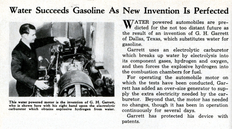
1935 – Inventor Henry Garrett patented a electrolytic carburetor and let a car run on tap water.
The late Henry “Dad” Garrett was a multi-talented Dallas inventor with a bent for electrical contrivances, and in 1935, he and his son, C.H. Garrett, patented and exhibited an automobile that ran on water — actually, on hydrogen after the water was broken down by electrolysis.
Dad Garrett was already famous for his work. In 1920 he set up WRR in Dallas, the world’s first municipal radio station, and was its first announcer. He was the first man to build a radio in his car, and he developed radio transmission from the car for police use. He also invented an automatic electric traffic signal, possibly the nation’s first.
On September 8, 1935, The Dallas Morning News first announced that the water-fuel concept worked — at least it worked for “several minutes,” the article reported. A few months later, Pathe’ News filmed the car driving along Garland Road with the driver stopping at White Rock Lake to fill the fuel tank with water before cruising off.
the Orion Project’s work on repeating Stanley Meyer’s success
![]()
On March 20th 1998, Stanley Meyer was killed, now, May 13th 2010, the O.P. is under attack, being suppressed. read about it.
Keep in mind:
The problem is very simply a billion dollar oil industry that is not going to let anyone threaten their dynasty.
parts list:
10 amp fuse, 1 glass jar, 2 steel bolts with 4 nuts, 1 yard of wire,
3 stainless steel plates, 2 nylon bolts with 5 nuts and 2 washers
Plus an EFIE ?:
“Most cars have oxygen sensors both before and after the catalytic converter. The ones downstream from the converter do not need to be treated. Their data is used to determine when the converter has gone bad, but are not used in the air/fuel calculations. EFIEs are only needed for all upstream oxygen sensors.”
“We actually don’t know how wide spread this practice is. However, once we started treating downstream sensors on models that we knew about, we’ve now found that many other vehicles that are not documented are also using down stream sensors. Ford “F” Series pickups are known to do this without documenting it, and we’re now finding at least some Ford cars are following suit. There are many other vehicles, that while they don’t use the rear sensors for air/fuel calculations, they still monitor the health of the upstream sensors, and if they are not both treated can cause mysterious engine trouble lights or cause the upstream sensors to not be used.”
“Due to this situation Fuel Savers have created the world’s first quad EFIE. That is a device that has 4 separate EFIE circuits and will treat 4 oxygen sensors.”
from www.hho2u.com/EFIE.html
a “Dry Cell” (re-circulating):
When the edges of the plates of a hho generator are submerged in the water/catalyst bath a great deal of the electrical current passes through the edges of the plates. This current is largely wasted in terms of HHO production.
from www.hho2u.com/HHO_DRY_CELL.html
The dry cell is an improvement but . . . see below: “my truck went from 13 to 30 mpg. It’s been on this truck 3 years now and it RUNS GREAT!!!” . . . a 130% improvement using wet cells.
Still most talk about – expect – only a 30% to 50% improvement (+/-)
We want to run on 100% hydrogen; no gasoline at all. Henry Garrett, Stanley Meyer, Daniel Dingel, and Dennis Klein did.
Alternately, running on fumes, a V8 truck getting only 13 mpg can get over 100 mpg! … not just 17 to 30. A 30 mpg 4-cylinder car can get about 400+ mpg! no wires, no plates, no battery connections . . . just a bottle with a little gas in the bottom. See our page “Run Your Car On Vapors-Fumes”.
The flash back arrestor is important:
Uploaded on Jan 17, 2009
toward the end, he deliberately ignites the hydrogen gas, several times (and gets a “pop” sounding explosion). Don’t try that with gasoline !!
Jan 11, 2010
Hydrogen generator from Household items
(down inside the bottle, the hydrogen explosion is dangerous – flying pieces of broken glass!)
“HHO Generator Video. Hydrogen On Demand Technology on my truck went from
13 to 30 mpg. It’s been on this truck 3 years now and it RUNS GREAT!!!”
King Hybrid VIDEO
“Hydrogen On Demand System being used on bone stock 2002 Chevy Silverado extended cab truck vehicle. Went from 13 mpg to 30 mpgs city. This truck never ran so good until this system was put in. You really need to experience it for yourself. Its been on this truck 3 years now and it RUNS GREAT!!! Don’t be “that guy”, you know, the last one to get on board. … Its just a matter of time before this movement is everywhere, then everyone will have it and it cant be silenced or stopped.” – King Hybrid
“HHO Generator – 97 Pontiac Sunfire Road Test” – went from 31.7 mpg to 56 mpg
Published on Apr 16, 2012
“Road test and gas mileage improvement results using an HHO on demand hydrogen generator. Car was a used, otherwise unmodified 97 Sunfire. Highway conditions were summer driving, with some hills. Speeds were on average between 105 to 110 KM / HR. It went from 31.7 mi/gal to 56 mi/gal” Almost double.
Diesel
“could save you more than 20% on Diesel fuel”, not great, but they got it to work:
with diesel fumes, do it with a bottle and some hose – save over 200%
another source:
“Our customers report 10-35% increase in diesel mileage”
http://www.hydrogen-generators-usa.com/hydrogen-generator.html
Diagrams
Figure 1

Till you are ready, forget the ignition and mount your own switch.
Figure 2

Figure 3
This experimenter goes to 30 amp. Still small enough but maybe overkill.

Figure 4
use 1 inch hoses and keep the pressure down

It is suggested you try this out to begin with on a second vehicle you own, one that you don’t need to live with everyday, until you perfect this technology.
This young man (Vox) mixed a little hydrogen in
with the gas as an experiment on his motorcycle.
motorcycle working with 100% water.HHO
In putting these plans into operation, you will be making use of your entire existing system except for the fuel tank and the catalytic converter.
take a look at this video generating hydrogen gas with a small amp.
http://www.youtube.com/watch?v=kvdPLJW06pw
The Plan
Build and install a low-cost alternative method for running your vehicle (internal combustion engine) on tap water, using off-the-shelf components.
This is supposed to be an efficient way to convert ordinary tap water into gaseous hydrogen and oxygen, and then burn these vapors in the engine, instead of gasoline.
This “minisystem” runs easily from your existing battery and electrical system, and it plugs into your air intake (manifold) with simple off-the-shelf fittings.
You will be installing a plastic water bottle, a fuse, a few metal plates.
The simplicity comes from its being an “on-demand” system requiring no hi pressure storage tanks or plumbing. You crank the gas pedal or throttle, and you electrically create more vapor for immediate consumption, on demand; low-high flow rate as needed, from idle to maximum power. The change is that you are using tap water as fuel, – a lot less (if any) of the traditional petroleum-based fuel.
H2O –> H2 + O2
Frequently Asked Questions
Q: How does it qualify as “free energy”?
A: If you’re paying someone for the water you use, then it is not strictly free. But it’s close enough.
Q: Is it safe?
A: It is safer than running on fossil fuel. You are no longer choking on your own emissions (health-wise). You are also no longer funding global terrorism. You are no longer running the extreme risk of a gasoline fire or explosion! Additionally, you will be installing a few simple safety devices, using current automotive standards.
To put it another way, Hydrogen is just as explosive as Gasoline but you are creating only small amounts of fumes, not tanks full of it like gasoline, and nothing that is left over, does any harm to the environment: When hydrogen ‘burns’ it becomes pure water.
H2 + O2 –> H2O
Q: What kind of performance can I expect?
A: Properly adjusted, your modified vapor-only fuel system will run cooler, and at a modestly higher power level. The mileage performance expected from this design ranges from 50-300 mpg (of water), depending on your adjusting skills and anywhere from 50% to no gasoline.
Q: Can I do the modification myself?
A: Why not? Can you drill 2 holes in a few small, thin, sheets of metal? run 2 wires from your car battery to your bottle with the electrodes in it . . . etc.?
Vid21 Washer Cell Hydrogen Generator (HHO, Brown’s Gas, Hydroxy)
Some different examples


I have a cell we made here with the plates spaced at 6 thousands of an inch and it blasts Hydrogen out of it like a volcano. A problem with this close of spacing is shorting out the plates and warping of the plates.
1/32 of an inch .0312 is what TLG Hydrogen is using on our dry cells. [.8 mm] This gap works great
http://www.tlghydrogen.com/tips_tricks/plategap.htm
You know that motorcycles use 6 or 12 volt batteries, and that is recognized here. Higher voltages require greater gaps.
So what does this have to do with cell spacing? Well consider the distance between your plates. If water is an insulator, then the more water you have between two plates, the higher the resistance will be between the plates. If you know anything about Ohms Law, an increase in Resistance causes electron flow to be reduced.
Electron flow is the amperage your cell is drawing. The farther apart your plates are, the less amps your cell will draw through the water. The closer the plates are, the more amperage your cell will draw. Amperage plays a big part in HHO production.
and the higher the voltage, the greater the electron flow.
Without it, your cell will produce squat; nothing.
If we add Electrolytes to the water, we will make the water conduct better by decreasing the Resistance between the plates. A decrease in resistance allows more current to flow; thus increasing the possibility of producing more HHO. A cell that has wide spacing can be made to produce just as much HHO as a cell with close spacing. The difference is going to be the amount of electrolytes added to the water. The cell with wide spacing will need larger amounts of electrolytes.
There is another factor to consider —– Heat. Cold water has more resistance than Hot water.
The hotter your water gets, the better it will conduct electricity. How many times have you been told that Electrolysis causes heat? Pay attention. The better water conducts electricity, the more amperage your cell is going to draw. Amperage is the movement of electrons. Movement is friction. Friction causes heat. So the more amperage you draw, the hotter your water is going to get.
The hotter the water gets, the more amperage it draws; which in turn creates more heat, which causes more current, which causes more heat.
Do you get the idea that amperage/heat needs to be controlled? You bet it does. If you don’t control it, it will run away from you.
Eventually blowing a fuse or tripping your cells circuit.
We have learned that a Pulse Width Modulator will help us with that problem.
As for plate spacing, we use 0.060 inches, or about 1.5 millimeters. That is about as close as possible and still get good bubble flow.
Closer spacing needs less electrolyte. It does not produce more gas or less gas; per say. Gas production is caused by amperage.
http://danieldonatelli.wix.com/hho-pocket-guide#!cell-spacing/c1nos
Remember This
There are a few things you should remember about gasoline:
Gasoline poisons the atmosphere and, it is very toxic and dangerous!
Gasoline versus Water
Most people are unaware that “internal combustion” is defined as “a thermo-vapor process” – as in “no liquid in the reaction.” Most of the gasoline in a standard internal combustion engine is actually consumed, (cooked, and finally, broken down) in the catalytic converter after the fuel has been not-so-burnt in the engine. Sadly, this means that most of the fuel we use in this way is used only to cool down the combustion process, a pollution-ridden and inefficient means of doing that. Lots of very explosive and flammable gasoline vs. a very small amount of hydrogen vapor.
How It Works
Water is added as needed to replenish and maintain the liquid level in the chamber. Electrolysis breaks 2(H2O) => 2H2 + O2. When the pressure reaches say 3-5 psi (with a 1.5 inch diam. hose), you turn the key and go. You step on the pedal, you send more energy to the electrodes, and thus more vapor to the cylinders; i.e. fuel vapor on demand.
You set the idle max-flow rate to get the most efficient use of power, and you’re off to the races.
In the big picture, your energy is coming from the tap water in an open system, as the latent energy in the water is enough to power the engine and hence drive the alternator and whatever belt-driven accessories. And the alternator is efficient enough to run the various electrical loads (10 – 20 amps), including the additional low current to run this vapor reaction. No extra batteries are required.
the Stanley Meyer generator
The Orion Project is trying to buy his equipment and recreate Stan’s success
there are many youtube videos on several inventors who have succeeded:
Daniel Dingel, from the Philippines
Read about and see Fox News broadcast from youtube (welding torch + car fuel): Denny Klein’s hydrogen generator and hydrogen torch – in Clearwater, Florida
read the article and patent on the Pacheco Generator
This guy is mixing a little hydrogen in with the gas
I personally built one of those hydrogen generators and installed it on my 1986 Buik SkyHawk. The car would only achieve 20 MPG before I installed the unit. After running the generator for only a week, and checking the fuel economy it now was 58 MPG. After running the unit for 1 year I was able to attain an average of 60 MPG with a top of 75.62 MPG. The Spark plugs were not changed and when removed were as clean as the day they were installed 3 years before.
One side effect was the increase in power that the engine had. A hill that I would have to drive up every time I went to the city would always slow the car down before, but after the hydrogen generator was installed the car would even accelerate going up the same hill. The reason for this could have been the hydrogen or a cleaner engine or a combination of both. Why I experencied this who knows and I really do not care about the techenical reason the only thing I know is that it worked.
I am not an engineer and have no idea why this worked and honestly do not care, I just know that there was a big increase in my cars fuel economy.
Winter up north in Canada also started as a bit of a problem with -40 degree weather but this was easily fixed by changing the electrolyte solution.
Gary K.
April 08 2014
electrical pulses, not brute force electrolysisWhere normal water electrolysis requires the passage of current measured in amps (10 or 20 where your battery produces over 400 and your alternator provides 50 amps or more – so miliamps is nice but it may not be worth the hassle), this cell achieves the same effect in milliamps. Furthermore, ordinary tap water [may] requires the addition of an electrolyte such as According to the witnesses, the most startling aspect of the Meyer cell was that it remained cold, even after hours of gas production. Meyer’s experiments, which he seems to be able to perform to order, have earned him a series of US patents granted under Section 101. The granting of a patent under this section is dependent on a successful demonstration of the invention to a Patent Review Board. Meyer’s cell seems to have many of the attributes of an electrolytic cell except that it functions at high voltage, low current rather than the other way around. Construction is unremarkable. The electrodes — referred to as “excitors” by Meyer — are made from parallel A witness team of independent UK scientifc observers testified that US inventor Stanley Meyer successfully decomposed ordinary tap water into constituent elements through a combination of high, pulsed voltage using an average current measured only in milliamps. Reported gas evolution was enough to sustain a hydrogen / oxygen flame which instantly melted steel. (How Denny Klein got started – see video) “We did notice that the water at the top of the cell slowly became discolored with a pale cream and dark brown precipitate, almost certainly the effects of the chlorine in the heavily chlorinated tap water…” … “We clearly saw how increasing and decreasing the voltage is used to control gas production. We saw how gas generation ceased and then began again instantly as the voltage driving circuit was switched off and then on again.” The use of a high voltage spike alone (1500 volts+), without the current being delivered through the liquid, will not cause the disassociation to take place. Once Stan’s unit was made to begin breakdown (which takes 6 to 8 seconds) he was able to reduce both current and voltage to miniscule proportions. There are two primary frequencies that produce the best results. They are: 14,372 Hz and 43,430 Hz. The former is about 50% more efficient, but it seems that just about any frequency between 9 KHz and 143,762 KHz works quite well. This is because the nature of the wave form ( a spike ) is rich in harmonics and one of them is bound to be close to one of the two primary frequencies. Meyer was apparently eating dinner at a Grove City, OHIO restaurant, when it is reported that he jumped up from the table, yelled that he’d been poisoned”, and rushed out into the parking lot, where he collapsed and died. Thieves came a week later and stole the the dune buggy and all of his experimental equipment, according to his twin brother, Stephen. Stan said while he was alive, that he was threatened many times and would not sell out to Arab Oil Corp’s. The Military was going to use this technology in their tanks, jeeps, etc. He had patents on his invention and was ready for production. See the Videos above. No gasoline, just water. Stanley said he was offered a billion dollars from an Arab to basically shelf his idea. Stan said, “No”. |
 plates of stainless steel placed in either flat or concentric arrangements. (see the washers, on the right, for one method) Gas production seems to vary as the inverse of the distance between them; the patents suggest a spacing of 1.5 mm produces satisfactory results.
STEP BY STEP CONSTRUCTION
OVERVIEW – Here is the suggested sequence of steps:
1. Build 2 or 3 electrodes and test their output in your bottle of water.
2. Temporarily insert the hydrogen and oxygen output tube into your engines air intake hose to verify the output with the different electrodes. Choose the smallest one that works.
3. Install-connect the bottle(s), limiter, and valves-fittings.
4. Run engine and adjust the accelerator-battery circuit as necessary for best performance.
6. Dump the now pointless catalytic converter and, if your exaust pipe is
not stainless steel already, later, replace it with stainless steel pipe sections.
PARTS LIST
plastic water bottle(s) with electrode and fittings.
battery-limiter, wiring, connectors, and epoxy.
1.5 inch flex-tubing, fittings and clamps.
pvc valves and fittings.
BASIC TOOLS
drill, screwdriver and pliers
wire-wrap, solder-iron and clippers
REACTION CHAMBER
Select bottles as shown in the diagrams. Make sure to drill-and-epoxy or tap threads thru the PVC components for all fittings. Set and control the water level in the chamber so that it well submerses the electrodes; yet leave some headroom to build up the hydrogen/oxygen vapor pressure. Use stainless steel wires inside the bottle or otherwise use a protective coating; use insulated wires outside. Ensure that the epoxy perfects the seal, or otherwise lay down a bead of water-proof silicone that can hold pressure.
The screw fitting may require soft silicone sealant, or a gasket; its purpose is to hold pressure
and allow periodic inspection of the electrodes. No leaks, no problems. Make sure you get a symmetric 1-5 mm gap between the stainless steel plates. The referenced literature suggests that the closer to 1 or 2 mm you get, the better. You will want to test your system before you epoxy the cap on.
Make your solder connections at the wire/electrode junctions nice, smooth, and solid; then apply a water-proof coating, e.g. the epoxy you use for joining the pipes to the screw cap. This epoxy must be waterproof and be capable of holding metal to plastic under pressure. You will want to test your float valve before you epoxy the cap on.
Throttle Control
We should be able to connect the accelerator cable to a rheostat (variable resistor) to the gas linkage (i.e. coupled to something at the throttle cable running to the carb or FI. If you make the attachment at the carb/FI, be sure to use a rheostat that can handle the engine temp cycles. Don’t go cheezy-cheapy, get one rated for long life and mechanical wear; mount it securely to something sturdy and stationary that will not fall apart when you step on the gas.
Control Range. The full throttle RANGE (idle-max) MUST control the vapor rate (duty). The resistor values at the throttle signal must allow the throttle signal voltage, say 1-4 Volt swing, to drive the VAPOR RATE. You will be using this voltage range to control speed and acceleration.
In this circuit, you will simply adjust to whatever voltage makes the most efficient vapor conversion.
You crank up the throttle and put more electrical energy into the electrodes; verify you can get everything you wanted.
potentiometers (POTs) have been mentioned: “Potentiometers and rheostats are made the same way, but rheostats are usually much sturdier, as they are generally used in high-power situations.”
ENGINE/EXHAUST TREATMENT
You could make max use of your current exhaust system by using it with your new deal until it rusts through, then have your mechanic or welder friend to fit a stainless steel exhaust pipe (no catalytic converter is required). But it could be easier and cheaper to send your existing exhaust system out for the ceramic treatment, and then simply re-attach it to the exhaust ports.
GENERAL
1. Do not discard or remove any of the old gasoline setup components, e.g. tank, fuel injectors, catalytic converter, unless necessary. Better to always leave an easy way to revert back to something that at least runs, just in case. Some people are leaving their gasoline setup completely intact, and switching back and forth at will, just to have a backup plan.
2. Set your throttle circuit so that you get minimum vapor flow at idle, and maximum vapor flow at full power without blowing the pressure relief valve. In this way, you control how ‘lean’ your mixture is by the strength of the voltage-amperage.
3. If you just don’t get enough power (at any throttle setting), it means that you need to (1) change the gap between the electrodes, (3) change the size (bigger) electrodes, or (4) use a higher amp fuse (last resort). Always use an output transistor, such as a MOSFET, that is rated for the voltage and current you need to get the job done. OK so you might have to play around with it some. Isn’t that where all the Fun is anyhow?
4. Build the canister(s) as tall as you can without compromising your ability to mount them conveniently in the engine compartment. This way, you can always make the electrodes bigger, if necessary without undue hardship (even do without the bubbler). Remember that anything in the engine compartment should be mounted in a bullet-proof, vibration and temperature tolerant fashion.
5. If you have to drill a thru-hole for wiring or plumbing thru metal, make sure to also install a grommet for protection against chafing. Always watch your chamber pressure range from IDLE (15-25 psi) – FULL POWER (30-60 psi). Set your safety-pressure relief-valve to 75 psi and make sure it’s rated higher.
6. Shut OFF the power switch and pull over if there is any malfunction of the system. Your engine will last longest when it still develops FULL POWER + at some minimum temperature that we are sure you can find, by leaning back the Vapor Flow and/or by making use of the water-vapor cooling technique. Keep good mpg performance records, and periodic maintenance/inspection. Keep it clean; save some money; clean the air; heal the planet; happy motoring; tell a friend; enjoy your freedom and self-empowerment.
7. If you install the water-vapor system (for lower operating temp/stress), you will want to lean the mixture (vapor/air) for minimum vapor flow rate to achieve any given throttle position (idle – max). Make sure that you get a minimum flow for IDLE and a good sufficient flow for MAX.
8. If you are concerned about the water freezing in your system, you can (a) add some 98% isopropyl alcohol and re-adjust the rheostat accordingly; or (b) install some electric heating coils.
HHOi under pressure into fuel rail may be the key to running vehicles on water and air
The onboard electrolysis unit, powered by the vehicle’s battery/alternator, produces an ionized hydroxy gas [HHOi] (the hydrogen and oxygen are not separated) that is injected under pressure (30 – 60 psi) into the fuel rail, and is able to keep the engine running.
The longest Rick has kept his Jeep going like this so far has been around 2.5 hours before it died. During that time, Rick was able to rev the engine via the accelerator pedal up and down, including to 3,000 rpms. It didn’t ever backfire. Somehow the car’s computer is able to compensate for the different fuel, and increase and decrease the speed the engine runs in response to the changing pedal position, just as it would if gasoline were running the vehicle. Perhaps the variation in airflow with the varying throttle positions with the pedal changes is what regulates the engine speed in this case. Also, the Jeep computer’s knock sensor automatically adjusts the timing of the engine to handle the HHOi gas. Rick was amazed to watch his gauge show the timing change on his Jeep.
The odd thing is that the rate of hydroxy gas production was constant, and was not governed to correspond to the increase or decrease in engine load. Nor is the rate of water consumption at a rate that present physics would predict would be needed for the water to be serving as fuel. Nor is the rate of electrical consumption in producing the hydroxy gas proportional to the amount of power manifest in idling the vehicle for that long. One of the pioneer researchers in the field, George Wiseman, points out that to be practical, the Brown’s gas (HHO or hydroxy) production will need to be nominally in proportion to the load requirement.
These attributes are similar to what Freddy reported, except he allegedly was running his friend’s pickup truck under load – driving down the road, speeding up and slowing down. Rick hopes to get to that point some time this week, with the help of an associate who is flying in to help out. If they get it running well, Rick would like to drive down to where I live and show it off to me.
… the hydroxy gas that both Freddy and Rick are allegedly producing is being called “HHOi”, the “i” symbolizing “ionized.” This is a term that James Sharp coined, and which Freddy has picked up
…Ionized Air as Fuel Contributor
On Saturday morning, Rick called me up to report that he tried running just straight air with an air compressor into the fuel rail on his Jeep, and that it actually idled for 2-3 minutes that way. He was wondering if whatever leftover fuel that is in the system might be enough to enable it to run that long.
Because of some other situations I know of, I postulated that it may be that the pressurized air itself could be contributing to the fuel component — with petrol in this case, and with HHOi in the above set-up.
I know of another researcher who claims that several years ago he was able to get his car to run on air alone after getting above 15 mph — that the pressure of the incoming air was enough, and there was enough energy in the air from solar power ionizing molecules in the air, and his engine had enough of a combustion efficiency to actually utilize the air as fuel under that low pressure and flow. He temporarily abandoned this effect to first pursue something not so disruptive and difficult for people to believe.
This week I got a phone call from another researcher, this one saying that he got his Papp engine running, and that the fuel source is . . . air. He doesn’t want coverage yet, but we are in process of checking out his claim, as he invited us to come see it. The reason I feel compelled to mention it here is that the Papp engine process may be similar to the effect we’re discussing here.
pesn.com/2010/09/27/9501707_HHOi_under_pressure_into_fuel_rail_running_vehicles_on_water_and_air/
Daniel Dingel
He has been running his car on 100% hydrogen
(hydrogen from water) for 30 years (?!)
REFERENCES
*Stephen Chambers ‘Apparatus for Producing Orthohydrogen and/or
*Parahydrogen’ US Patent 6126794, uspto.gov
*Stanley Meyer ‘Method for the Production of a Fuel Gas’ US Patent 4936961, uspto.gov
*Creative Science & Research, ‘Fuel From Water’, fuelless.com
*Carl Cella “A Water-Fuelled Car” Nexus Magazine Oct-Nov 1996
*Peter Lindemann “Where in the World is All the Free Energy”, free-energy.cc
*George Wiseman “The Gas-Saver and HyCO Series” eagle-research.com
*C. Michael Holler “The Dromedary Newsletter” and “SuperCarb Techniques”
*Stephen Chambers “Prototype Vapor Fuel System” xogen.com
He has never tried any mixture of gas and water – he does not think it is possible. His car consumes about 1 quart (liter) per hour, he says. Conservatively 1 gal. should take you 120 to 240 miles? (30 to 60 mph) That makes water a lot better than gasoline on volume alone, not to mention price!
He is said to have converted 100 cars to run on water.
Ronn Motors, Dennis Klein, Francisco Pacheco, Stanley Meyer, Daniel Dingel and others have all done it with their designs
see our page, The history of Water Powered Cars
With Daniel’s death, it comes out that, rather than give it to the world freely, he got frustrated (?) and took a buy-out, giving his car and hho generator to a friend, Pete, to publicize after his death.
See our page on Daniel Dingel 1968
or his friend’s site at www.dinglefoundation.com/hhoblog
many more videos:
UTube videos on building your own water to hydrogen generator / HHO Water Fuel
Other Options:
Magnetism:
There, finally, seems to be some significant progress toward powering a generator with a magnet motor. This goes a long way toward reducing the amount of battery storage needed to power an electric motor/vehicle.
see A Few Magnet Motors
Vaporization:
“During our interview the eager young inventor revealed how he had discovered his fuel system by accident; “I was messing around with a lawn-mower when I accidentally knocked a hole in its fuel tank. I put a vacuum line running from the tank straight into the carburetor inlet (he removed the carburetor). I just let it run and it kept running and running but the fuel level stayed the same. I got excited. The lawn-mower was running without a carburetor and getting tremendous efficiency.”
see Tom Ogle carb.
The Nelson Pogue carburetor caused a sell-off of oil stocks in 1936.
9-14-2012
We cannot tell how much it will help, If Daniel Dingel‘s HHO system is easier or not, but upon his death, he instructed a friend, Pete, to post how to make his generator.
See our page: Daniel Dingel 1968
or his friend’s site at www.dinglefoundation.com/hhoblog
Keep in mind that using water for fuel is only to “buy time” till
high-density batteries as good as or better than lithium-ion can provide 300 mi/charge or better. (already available in Tesla Motors “S” model) (as good as or better than gasoline powered vehicles) When we can tap the unlimited electricity in radiant energy all around us, then little or no fossil fuels will be needed for transportation or power generation of any kind.
Electric vs. Internal Combustion
The internal combustion engine is a device that inherently tries to destroy itself: numerous explosions drive its pistons up and down to turn a shaft. A shaft rotating at 6,000 revolutions/minute produces 100 explosions every second. These explosions in turn require a massive vessel to contain them-typically a cast-iron cylinder block.
Additional systems are necessary:
1 A cooling system to keep the temperatures within a safe operating range.
2 An exhaust system to remove the heated exhaust products safely.
3 An ignition system to initiate the combustion at the right moment.
4 A fueling system to introduce the proper mixture of air and gas for combustion.
5 A lubricating system to reduce wear on high-temperature, rapidly moving parts.
6 A starting system to get the whole cycle going.
It’s complicated to keep all these systems working together. This complexity means more things can go wrong (more frequent repairs and higher repair costs).Unfortunately, the internal combustion engine vehicle’s legacy of destruction doesn’t just stop with itself. The internal combustion engine is a variant of the generic combustion process. To light a match, you use oxygen (O2) from the air to burn a carbon based fuel (wood or cardboard matchstick), generate carbon dioxide (CO2), emit toxic waste gases (you can see the smoke and perhaps smell the sulfur), and leave a solid waste (burnt matchstick). The volume of air around you is far greater than that consumed by the match; air currents soon dissipate the smoke and smell, and you toss the matchstick.
Today’s internal combustion engine is more evolved than ever. However, we still have a carbon-based combustion process that creates heat and pollution. Everything about the internal combustion engine is toxic, and is still one of the least-efficient mechanical devices on the planet. Unlike lighting a single match, the use of hundreds of millions (soon to be billions) of internal combustion engine vehicles threatens to destroy all life on our earth.
While an internal combustion engine has hundreds of moving parts, an electric motor only has ONE.
That’s one of the main reasons why electric cars are so efficient!
http://www.evworld.sg/EducationICE.htm
“Maintaining an electric car, according to some estimates, will cost about one-third the current cost of maintaining a gasoline-powered car. The bottom line is this: Electric cars require considerably less maintenance than gas-driven cars.”
http://www.howstuffworks.com/will-electric-cars-require-more-maintenance.htm
The Francisco Pacheco Hydrogen Generator
Daniel Dingel, 1968
Dennis Klein’s Gas Engine Water additive
Stanley Meyer’s water powered car
Today
For detailed instructions on how to get 200-to-400 mpg fuel efficiency (run your car on fumes) see our page
Run your car on vapors-fumes
the T fitting: 1 or 1.5 inch diam. about $3
1 or 1.5 inch diam. vinyl tubing: about $3/ft
from your hardware store
ask any mechanic,
“Any car can idle {and accelerate} on fumes. I (and countless other shadetree mechanics) have started, idled and revved quite a few engines using only a rag with some gasoline on it (don’t try this at home).” – Ike B.
“We just squirt a little gas into the carb and run the engine long enough to do any testing.” – owner of an auto repair shop
put a little gas in the bottom of a bottle and run a hose from it to the intake of the engine, no other fuel needed. it will run for hours.

I built a “water engine” as a science fair project in 1969. I used a lawn mower engine and removed the carb. When it was running I noticed that after about 20 minutes the exhaust pipe was still cool enough to hold in my hand. My problem was that the electrodes transferred their metal from one electrode to the other thus destroying both electrodes. Later I did research to which metals would stay intact during electrolysis rather than electro-plating. I also tried to keep the H2 and O2 separate which is not practical with the closely spaced plates you are using. H2 can also be produced by passing steam over hot iron but controlling it has been a problem