


updated 07-26-2016
How To Build Your Own Generator that generates electricity free
“Although originally suggested by Nikola Tesla in 1905, only a few permanent magnet motors-generators have been designed, that is, magnet motors where the power comes from the magnets, not an external, exaustable supply of electricity.”
“Engineers of Hitachi Magnetics Corp. of California have stated that a motor-generator run solely by magnets is feasible and logical but the politics of the matter make it impossible for them to pursue developing a magnet motor or any device that would compete with the energy cartels.”

“Electric power is everywhere present in unlimited quantities and can drive the world’s machinery without the need for coal, oil, or gas.”
– Nikola Tesla
Today scientists say the universe is 60% “Radient/Dark” energy. (see our pages on “Tesla, Radiant Energy,1,2,3”)
“Writing on June 10th, 1902 to his friend Robert U. Johnson, editor of Century Magazine, Tesla included a clipping from the previous day’s New York Herald about Clemente Figueras [Figuera], a woods and forest engineer in Las Palmas, capital of the Canary Islands, [and for many years professor of physics at St. Augustine´s College, Las Palmas,] who had invented a device for generating electricity without burning fuel.” [carbon/fossil-based] instead, getting energy from the “atmosphere”, environment, space our sun and planets travel in.
Spanish Patent and Trademark Office
First of 4 patents (30375-30378) filed while living in Canary Island (1902)
• Patent number: 30375. Title: A process for obtaining electrical currents entirely the same as those given by current dynamos. Date of application: 09/20/1902. Applicant: Figuera Urtáiz, Clemente / Blasberge, Pedro.
This announcement in the paper prompted Tesla, in his letter to Johnson, to claim he had already developed such a device and had revealed the underlying physical laws.
from www.alpoma.net/tecob/?page_id=8258
Other U.S. patents have been filed – see Ammann, Hendershot, Hubbard, and others, however, only Tesla understood the Physics involved.
If you have a gasoline fueled generator, you can modify it to run on less than one tenth, 1/10, the gas. It is very easy to do – a bottle and some hose – and is a significant step toward a fuel free environment.
see our page “Run Your Car On Vapors”
Relativity
Concrete proof that relativity can be violated can be found in George Gamow’s watershed book Thirty Years That Shook Physics. Gamow, one of the founding fathers of quantum physics, tells us that in the mid-1920’s, Goudsmit and Uhlenbeck discovered not only that electrons were orthorotating, but also that they were spinning at 1.37 times the speed of light. Gamow makes it clear that this discovery did not violate anything in quantum physics, what it violated was Einstein’s principle that nothing could travel faster than the speed of light.
No physicist talks about this anymore. What this means is that the entire evolution of 20th and nascent 21st century physics is evolving ignoring this key Goudsmit and Uhlenbeck finding. The ramifications suggest that elementary particles, by their nature, interface dimensions. Because they are spinning faster than the speed of light, the idea is that they are drawing this energy from the ether, a pre-physical realm, and converting the energy into material form.
– Nikola Tesla
See our page “Tesla’s Unk. Manuscript”
C. Earl Ammann:
The young inventor, C. Earl Ammann, today, Monday, August 8, 1921, demonstrated his invention by attaching it to an old automobile and running it about the city.Lester Hendershot
In 1960, Lester Hendershot’s device (now called a ‘magnatronic generator’) was researched by the U.S. Navy’s Office of Naval Research. The generator was reported to have lit a 100-watt lamp by ‘induced radio frequency energy.’ The project ended when Hendershot committed suicide.
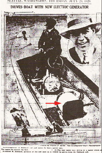
Alfred Hubbard:
In 1920, at the age of 19, Alfred Hubbard built a coil and motor that ran his boat 10 knots an hour on Portage Bay in Seattle. He called this ‘fuelless’ unit an ‘atmospheric power generator.’ Hubbard claimed it could operate for years; drive a large car; light an office building; and fly a plane around the world nonstop. Little is known about the Hubbard Coil. He was forced into obscurity because of what his motor would do to the present industries. “Since Alfred Hubbard worked with Tesla for a short period, it seems likely that his transformer is based on [information from] Tesla.”
T. Henry Moray
A Doctor of Electrical Engineering, T. Henry Moray wrote the book ‘The Sea of Energy in Which the Earth Floats’ in 1960. It contains results of a 50 year study with another type of ‘atmospheric energy collector.’ During FDR’s reign, Moray became the chief engineer of the western branch of the Rural Electrification Agency. He built a device that weighed 55 pounds and produced up to 50,000 watts. An ignorant co-worker was so enraged by the strange principles Moray tested, that he destroyed the machine. By today’s standards, the loss would be over a million dollars. Moray wrote that ‘frequencies maybe developed which will balance the force of gravity to a point of neutralization.’
Moray: ‘It was during the Christmas holidays of 1911 that I began to realize the fact that the energy I was working with was not of a static nature but of an oscillating nature, and that the energy was not coming out of the Earth but that it rather was coming in to the Earth from some outside source.’Ed Gray
Edwin Gray Sr., 48, has fashioned working devices that could:
Power every auto, train, truck, boat and plane that moves in this land — perpetually.
Warm, cool and service every American home — without erecting a single transmission line.
Feed limitless energy into the nation’s mighty industrial system — forever.
And do it all without creating a single iota of pollution.
“He flicked a switch and the tiny battery sent a charge into the capacitors. He then plugged in six 15-watt electric bulbs on individual cords — and a 110-volt portable television set and two radios. The bulbs burned brightly, the television played, and both radios blared — and yet, the small battery was not discharging.”


Ed Gray’s R. E. Motor
Another potentially valuable magnet-motor
invention and its suppression

see 2 page story and patents of Edwin V. Gray’s
1975 Radiant energy motor:
“Pulsed Capacitor Discharge Electric Engine”
See you the pyramid that is in the center there? That must rotate, and there must be magnets … in the corners of the larger pyramid. … The outer pyramid must have another at the bottom pointing down, …And quartz must be attached, … a sheet of quartz to store the frequency. [a capacitor to store the electrical charge?] with your magnets to balance. … Someone has already built it, by the way, so it should be pretty easy … Not a big expense either. … It’s only only … this big … [about a foot in diameter] . . . Everyone should have one in their yard. If you make it and succeed, give it away . . . Keep making them and giving them away. . . . Maybe then you’ll stop polluting.
from Shining the Light II by Light Technology Research, ~ Arthur Fanning; pg. 136-137
There was no picture with this statement so it is hard to picture it in our minds. If anyone can get it to work, let us know how and help start a movement – a magnet motor in every yard!
Directory: Motor-Generator Self-Looped with Usable Energy Left Over
Picture this. You have a motor turning a larger output generator, and the generator is producing enough energy to keep the motor running, as well as enough left over to power other things. (It’s a little more complicated than this, but that is the general idea.) All you need to get it going is a starter motor, temporarily, like on an automobile engine, and once the system is going, it stays going, unless it is shut off.
Sounds like a clear case of violating the law of conservation of energy, right?
Apparently not.
September 16, 2013 Update: Now we know of 26 individuals/groups that have come up with this independent from one another. Some of these are likely to be bogus, but not all.
see the directory listing
how to build a self running generator
Proof of Concept
Disproof of corporate and (bought) government denials
Variations on a Magnet Motor
Evolution of Perpetual Motion, WORKING Free Energy Generator

Proof of Concept

A group of these could be
mounted on a rotating disc?
the 2 below are similar

Dual Geared Wheels

using an iron bar for a magnetic shield
Permanent magnets on both sides of an iron shield are attracted to the shield and only weakly to each other at close proximity to the shield.

The simplest, cheapest, ideas are the best.
Radio Shack sells 1″ and 1.5″ bar magnets. However, many bar magnets are a lot cheaper on the web. Do a google search.
you may find a pkg of 50 “magnetic buttons” at Walmart for about $6.
Take a wheel off an old toy, an old roller skate, … or find a hardware store which sells wheels (caster or small fly-wheels?) or a place which sells parts (wheels) for R.C. cars, and buy a couple.

In 1893, Tesla applied for a patent on an electrical coil that is the most likely candidate for a non-mechanical successor of his energy extractor. This is his “Coil for Electro-magnets,” patent #512,340. It is a curious design, unlike an ordinary coil made by turning wire on a tube form, this one uses two wires laid next to each other on a form but with the end of the first one connected to the beginning of the second one.
In the patent Tesla explains that this double coil will store many times the energy of a conventional coil.
http://www.bibliotecapleyades.net/tesla/lostjournals/lostjournals07.htm
Capacitors are occasionally referred to as condensers.
This is now considered an antiquated term.
A light-weight super high density capacitor
to replace heavy batteries in an electric car
Nikola Tesla US patent # 512,340
Nikola Tesla: COIL FOR ELECTRO MAGNETS.
No. 512,340. Patented Jen. 9,1894.

SPECIFICATION forming part of Letters Patent No. 512,340, dated January 9, 1894. Application filed July 7.1893. Serial No. 479,804.
Be it known that I, NIKOLA TESLA, a citizen of the United States, residing at New York, in the county and State of New York, have invented certain new and useful improvements in Coils for Electro-Magnets and other Apparatus, of which the following is a specification, reference being had to the drawings accompanying and forming a part of the same.
In electric apparatus or systems in which alternating currents are employed the self induction of the coils or conductors may, and, in fact, in many cases does operate disadvantageously by giving rise to false currents which often reduce what is known as the commercial efficiency of the apparatus composing the system or operate detrimentally in other respects. The effects of self-induction, above referred to, are known to be neutralized by proportioning to a proper degree the capacity of the circuit with relation to the self-induction and frequency of the currents. This has been accomplished here-to-fore by the use of condensers [capacitors] constructed and applied as separate instruments.
My present invention has for its object to avoid the employment of condensers [capacitors] which are expensive, cumbersome and difficult to maintain in perfect condition, and to so construct the coils themselves as to accomplish the same ultimate object.
In order to attain my object and, to properly increase the capacity of any given coil, I wind it in such way as to secure a greater difference of potential between its adjacent turns or convolutions, and since the energy stored in the coil-considering the latter as a condenser [capacitor], is proportionate to the square of the potential difference between its adjacent convolutions, it is evident that I may in this way secure by a proper disposition of these convolutions a greatly increased capacity for a given increase in potential difference between the turns.
Figure l is a diagram of a coil wound in the ordinary manner. Fig. 2 is a diagram of a winding designed to secure the objects of my invention.

Let A, Fig. 1, designate any given coil the spires or convolutions of which are wound upon and insulated from each other. Let it be assumed that the terminals of this coil show a potential difference of one hundred volts, and that there are one thousand convolutions; their considering any two contiguous points on adjacent convolutions let it be assumed that there will exist between them a potential difference of one-tenth of a volt. If now, as shown in Fig. 2, a conductor B be wound parallel with the conductor A and insulated from it, and the end of A be connected with the starting point of B, the aggregate length of the two conductors being such that the assumed number of convolutions or turns is the same, viz., one thousand, then the potential difference between any two adjacent points in A and B will be fifty volts, and as the capacity effect is proportionate to the square of this difference. The energy stored in the coil as a whole – will now be two hundred and fifty thousand times as great Following out this principle, I may wind any given coil either in Whole or in part, not only in the specific manner herein illustrated, but also in a great variety of ways, well known in the art, so as to secure between adjacent convolutions such potential difference as will give the proper capacity to neutralize the self-induction for any given current that may be employed. Capacity secured in this particular way possesses an additional advantage in that it is evenly distributed, a consideration of the greatest importance in many cases, and the results, both as to efficiency and economy, are the more readily and easily obtained as the size of the coils, the potential difference,
or frequency of the currents are increased.
Coils composed of independent strands or conductors wound side by side and connected in series are not in themselves new, and I do not regard a more detailed description of the same as necessary. but heretofore, so far as I am aware, the objects in view have been essentially different from mine, and the results which I obtain even if an incident to such forms of winding have not been appreciated or taken advantage of.
In carrying out my invention it is to be observed that certain facts are well understood by those skilled in the art, viz: the relations of capacity, self-induction, and the frequency and potential difference of the current. What capacity, therefore, in any given case it is desirable to obtain and what special winding will secure it, are readily determinable from the other factors which are known.

What I claim as my invention is –
1. A coil for electric apparatus the adjacent convolutions of which form parts of the circuit between which there exists a potential difference sufficient to secure in the coil a capacity capable of neutralizing its self-induction, as herein before described.
2. A coil composed of contiguous or adjacent insulated conductors electrically connected in series and having a potential difference of such value as to give to the coil as a whole, a capacity sufficient to neutralize its self-induction, as set forth.
NIKOLA TESLA.
Witnesses:
Robert F. Gaylord,
Parker W. Page
http://www.google.com/patents/US512340

1979
Howard Johnson created one. He has arranged a set of permanent magnets on the rotor and a corresponding set – with different spacing – on the stator. One simply has to move the stator into position and rotation of the rotor begins immediately.
His invention was vandalized; his work suppressed:
“He’s had numerous additional setbacks over the years after his working unit was vandalized by thieves that broke into Howard’s shop and stole only the magnets off that model, leaving many $thousands worth of other material nearby untouched.”
see Howard Johnson’s permanent Magnet Motor
Some basic observations concerning magnets
- Two magnets repel further than they attract because of friction and inertia forces, however, Using magnets to repel tends to weaken them as it causes more misalignment of the domains.
- Most of our energy comes directly or indirectly from electromagnetic energy of the sun, e.g. photosynthesis and watercycle of ocean to water vapor to rain or snow to ocean.
- Magnetic energy “travels” between poles at the speed of light.
- Permanent magnets on both sides of an iron shield are attracted to the shield and only weakly to each other at close proximity to the shield.
- Permanent magnets are ferrous metals. The attraction is an inverse square force.
- Magnetic energy can be shielded.
- The sliding or perpendicular force of a keeper is much less than the force in the direction of the field to remove the keeper.
- Most of the magnetic energy is concentrated at the poles of the magnet.
- A permanent magnet loses little strength unless dropped or heated. Heating misaligns the magnetic elements within the magnet.
- If a weight lifted by a permanet magnet is slowly increased, the lifting power of the magnet can be increased until all the magnetic domains in the magnet are aligned in the same direction. This becomes the limit.
“It is absolutely essential to know that the universe is governed by perpetual motion, from the atom to the galaxy for “eternity past” and for “eternity future”, producing its own movements independently without interruption.”
Alfred Hubbard’s Generator
Howard Johnson’s permanent Magnet Motor
Tesla’s Electric Car
Tesla, Radiant Energy, page 1
Tesla, Radiant Energy, page 2
Tesla, Radiant Energy, page 3
Tesla’s Biography
Alternatively, for detailed instructions on how to make your vehicle extremely fuel efficient ( to run your car on fumes ) see our pageRun your car on vapors

the T fitting: 1-1/2 inch diam. = $3
1-1/2 inch diam. vinyl tubing = $3/ft

Run Your Car On Vapors
Charles Pogue Carb.
Tom Ogle Carb.
Build Your Own Hydrogen Generator
I believe a magnet motor is achievable and would be the ultimate 0 emissions engine for automobiles. However, after reading this page and seeing all the good ideas and attempts to example such a motor, one can only wonder why it is hasn’t been pursued and proven out to be the best idea since slice bread?